RIMS Controller
Each component of the controller was specifically selected to control a RIMS brewery system and the PCB board was custom designed to accommodate them. The primary microprocessor is the Microchip '74 series, and is programmed in assembly language. The A/D converter and RS-232 driver are manufactured by Maxim.
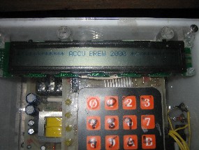
Upon powering the controller, ACCU BREW 2000 is displayed. Upon hitting any key, the main menu (Display Menu - Input Menu - Start/Stop) is displayed. Pressing NEXT scrolls the menu, pressing ENTER goes forward, and pressing CLEAR goes backwards. See Controller Menu for the controller's various options. A ten-key keypad is used to input numerical data along with the ENTER and CLEAR key. In addition to using the Input function, keys 1 and 7 are used to directly increase and decrease pump speed. Dedicated keys are included to enable the mash heater, liquor heater, and pump heater, and LEDís are used to indicated whether each of these are activated.
All functions of the controller are housed in a single controller. The controller has a 16 key keypad and 40-character display for as a user interface. A RS-232 port is available for exporting data to 3rd party systems (i.e. Excel). Two temperature sensors are directly monitored consisting of pump discharge temperature (i.e. mash) and liquor temperature. Pump speed, liquor heater, and mash heater are directly controlled by the device, and 120 volts is directly accepted.
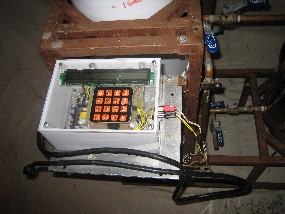
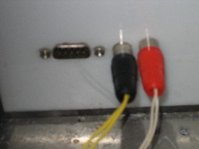
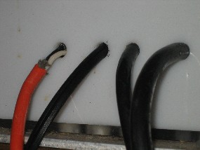
Both the mash (actually pump discharge) temperature and liquor temperature have resolution of 0.01 degrees Fahrenheit. Thermistors are measured using 14-bit A/D converters, and a lookup table to linierize the signal. A 2nd order hardware filter is used to eliminate most noise. A least squares regression software filter is implemented to eliminate remaining noise and calculate rates of change.
Both the mash and liquor heaters have 256 distinct power levels. A zero-crossover triac sources between zero to 255 60-hertz half-cycles using a duty cycle of 255 60-herzt half-cycles. Filters are incorporated to prevent power spikes.
The pump has 65,536 distinct power levels, however, software coverts this to 100 levels. An opticouple measures when the AC cycle crosses zero, and a triac is activated at the appropriate time. Filters are incorporated to prevent power spikes and damage to the pump.
The high voltage circuits (heater control, pump control, and power supply) and the low voltage circuits (microprocessor, display, keypad, and communication interface) are isolated from one another using opticouples and transformers.
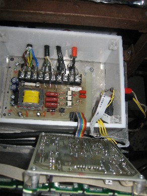
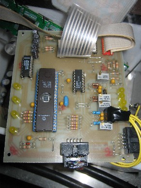
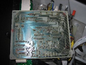
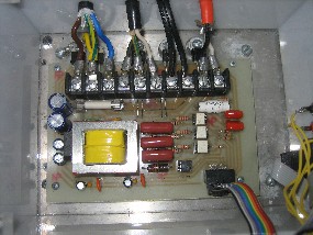
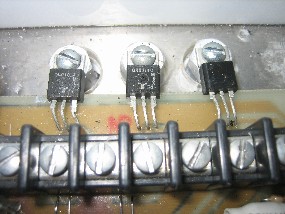
Power control devices are heat sunk to the chassis to efficiently dissipate heat. A terminal strip is utilized to connect 120 volt power as well as mash heater, liquor heater, and pump loads.
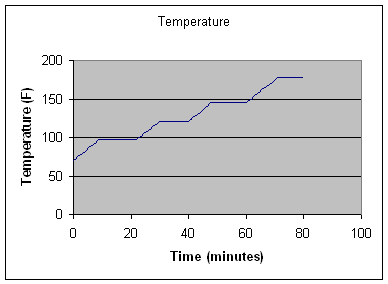
For archive purposes, data may be exported to a CSV file and imported input a 3rd party system such as Excel.
For schematic drawings, see the following:
- Main Schematic
- Power Supply Schematic
- Mash Heater Schematic
- Liquor Heater Schematic
- Pump Schematic
- Mash and Liquor Temperature Schematic
- Data Acquisition Schematic
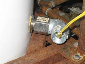
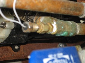
Thermistors are used to monitor both pump discharge (mash) temperature and liquor tank temperature. While thermistors are inherently nonlinear, they are more responsive than RTDís and thermocouples and nonlinearity is addressed by the controller.
